Skip to content



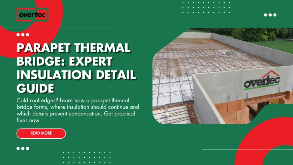
A parapet thermal bridge is one of the easiest details to overlook when designing a highly insulated building envelope.
The roof may have continuous insulation. The external wall may have excellent thermal performance. Windows may use thermally broken frames. Yet heat can still escape through the junction where the roof, wall and parapet meet.
This happens because the parapet often interrupts the ideal insulation layer. A structural wall, concrete upstand, metal fixing or other relatively conductive component can pass through or around the insulation, creating a roof edge thermal bridge.
The consequence is not limited to higher heat loss. Poorly designed parapet insulation can create cold internal surfaces, increase parapet condensation risk, complicate waterproofing and reduce the overall energy performance of an otherwise efficient building.
The solution is therefore not simply to “add more insulation”. The insulation has to remain as continuous as possible around the roof-to-wall junction while the structural, waterproofing and architectural requirements are still satisfied.
This guide explains how a parapet thermal bridge forms, how to identify vulnerable details, where insulation should continue, when a thermal break may be appropriate, and how prefabricated parapet systems can reduce some of the difficulties associated with conventional construction.
Quick Answer: What Is a Parapet Thermal Bridge?
A parapet thermal bridge occurs when heat flows more easily through the roof-edge/parapet junction than through the surrounding insulated building envelope. This commonly happens where structural materials interrupt continuous insulation.
| Topic | Quick Answer |
| What is a parapet thermal bridge? | A localized area of increased heat transfer at the parapet and roof/wall junction. |
| Main cause | Interruption or thinning of continuous insulation by structural or construction elements. |
| Typical location | Roof-to-wall junction, parapet wall, coping and structural connection. |
| Main consequence | Increased heat loss and lower internal surface temperatures. |
| Condensation concern | A sufficiently cold internal surface can increase condensation and mould risk. |
| Main design response | Maintain continuous insulation and minimise conductive paths through the envelope. |
| Thermal break | Can reduce heat flow through specific structural connections where appropriate. |
| Best design approach | Coordinate structure, insulation, waterproofing and parapet detailing from the beginning. |
What Is a Parapet Thermal Bridge?
A thermal bridge is a part of the building envelope where heat transfer is locally higher than in the surrounding construction. At a parapet, this often occurs because the geometry changes abruptly and the insulation layer has to navigate a complicated roof-edge junction.
A conventional parapet can connect the external wall to the roof structure while also carrying coping, façade finishes, waterproofing or protective elements. If the structural material crosses the insulation layer, it can provide a more conductive route for heat than the insulated wall or roof assembly.
The problem becomes more significant in highly insulated buildings. When the surrounding envelope has a low thermal transmittance, a relatively small weak point can have a noticeable effect on local surface temperatures and junction performance.
The correct way to assess the detail is therefore to look at the complete roof edge insulation strategy, rather than evaluating the parapet wall independently.
How Does a Thermal Bridge Form at a Parapet?
The most common mechanism is an interruption in the continuity of insulation. For example, a concrete parapet wall can extend upward from a structural slab while the roof insulation terminates against it. The concrete then creates a direct conductive path between warmer and colder parts of the building envelope.
Geometry also matters. Even when insulation is technically present, sharp corners, reduced insulation thickness or poorly positioned layers can concentrate heat flow. A roof edge thermal bridge is therefore partly a material problem and partly a geometric problem.
Fixings can create smaller thermal bridges as well. Metal brackets, anchors, rails and other conductive components can bypass insulation. Individually these elements may have limited influence, but repeated connections can become relevant in a detailed thermal analysis.
Why Is the Roof Edge Particularly Vulnerable?
The roof edge combines several systems in a relatively small area. The roof membrane needs to turn up, insulation needs to remain continuous, the wall needs to be structurally supported, and the parapet needs to resist environmental loads.
These requirements can conflict. For example, increasing the parapet insulation may improve thermal performance but reduce space for membrane termination or change the position of the coping. Moving the insulation may improve one junction while creating another discontinuity.
The roof edge is also exposed to strong temperature differences. The exterior side can become very cold during winter while the interior side remains heated. This makes poorly insulated junctions important when assessing parapet energy efficiency and condensation risk.
A good detail therefore resolves the complete junction rather than treating thermal insulation as an isolated layer.
Why Does Parapet Thermal Bridging Matter?
The first consequence of a thermal bridge is increased heat flow. The actual energy impact depends on the geometry, materials, length of the junction and temperature difference, so the effect cannot be determined from parapet dimensions alone.
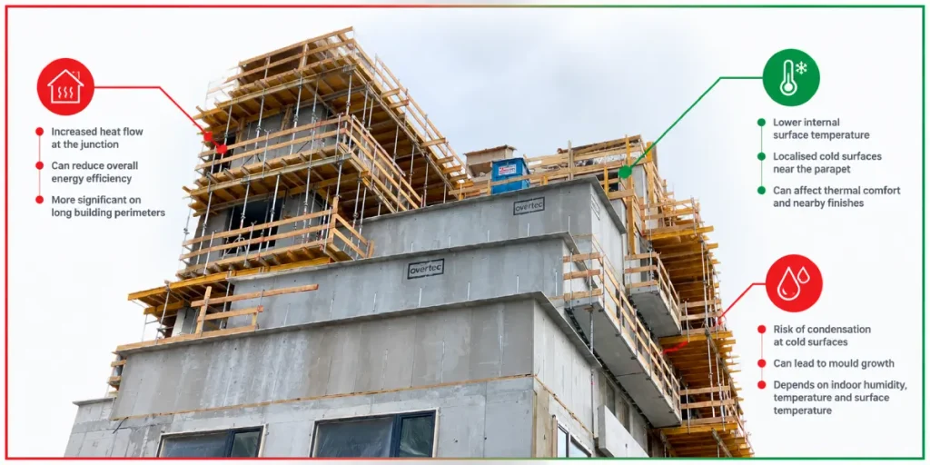
For energy-efficient buildings, however, junctions matter because the roof and wall assemblies may already be highly insulated. A building can have excellent nominal insulation values while still suffering from weaker performance at repeated linear junctions.
Thermal bridging also affects the internal surface temperature. A cold internal corner or wall surface can become significantly colder than the surrounding construction even when the room itself is comfortably heated.
This is why a parapet thermal bridge should be considered both an energy issue and a building-physics issue.
Heat Loss and Energy Efficiency
A roof edge thermal bridge creates additional heat flow through the junction. Unlike heat transfer through a large uniform wall or roof area, this heat flow is concentrated around the junction and is generally assessed separately during detailed building-envelope calculations.
The impact becomes particularly relevant when the parapet runs around a large building perimeter. A relatively small thermal weakness repeated over hundreds of metres can become more significant than an isolated connection.
For low-energy buildings, the objective is therefore not simply to increase insulation thickness. It is to create a continuous thermal envelope with as few unnecessary interruptions as practical.
Internal Surface Temperature and Comfort
A thermal bridge can reduce the temperature of the interior surface around the parapet junction. This may create a colder strip or corner even though the main wall and roof surfaces remain warm.
Occupants may notice this as a localised cold surface or discomfort near the building perimeter. In some cases, furniture or finishes placed close to a cold junction can also be affected by the altered local environment.
The important point is that thermal comfort cannot always be judged from the nominal U-value of the wall or roof. Junction details need separate consideration because their geometry and material arrangement can produce different surface temperatures.
Thermal Bridge Condensation and Mould Risk
One of the more serious consequences of poor thermal detailing is thermal bridge condensation. If the internal surface becomes sufficiently cold relative to indoor air conditions, moisture can condense on or near the surface.
The risk depends on indoor humidity, indoor temperature, outdoor temperature, surface temperature and the duration of the conditions. It should therefore be assessed rather than assumed.
The practical design response is to keep the internal surface temperature sufficiently high by maintaining insulation continuity and controlling the geometry of the junction. Where necessary, hygrothermal or two-dimensional thermal analysis can provide a more reliable assessment than a simple insulation-thickness calculation.
The Role of Parapet Insulation
Parapet insulation should be considered as part of the building’s continuous thermal envelope. The exact arrangement depends on whether the parapet is structural, non-structural, insulated on one or both faces, and how the roof and wall systems are constructed.
A common mistake is to insulate the main roof effectively but allow the insulation to stop abruptly at the parapet. The roof may then have excellent thermal performance while the edge creates a concentrated thermal weakness.
The same principle applies to the wall. If external wall insulation stops below or beside a conductive parapet connection, the insulation layer has effectively been interrupted at one of the most geometrically complicated parts of the envelope.
Continuous Insulation at the Parapet
The preferred principle is simple: keep the insulation layer continuous wherever the construction permits it.
At the roof edge, this can mean carrying the roof insulation toward and around the parapet junction while coordinating it with the wall insulation. The exact build-up will depend on the roof membrane, structural slab, parapet material and façade system.
Continuity is more important than simply specifying a high insulation value for one individual component. A thick insulation board placed beside an exposed structural connection does not automatically eliminate the thermal bridge.
Parapet Wall Insulation Detail
A good parapet wall insulation detail must show more than the insulation itself. It should demonstrate how the insulation connects to the wall, roof, waterproofing membrane and parapet termination.
The detail should also identify areas where insulation becomes thinner. These reductions are often caused by coping, parapet wall flashing, fixings or changes in construction thickness and can be overlooked during early design.
For complicated projects, the detail should be reviewed in section rather than only in plan. A section makes it much easier to see whether the thermal envelope is genuinely continuous.
Roof Edge Insulation
Roof edge insulation has to perform alongside waterproofing and drainage. The membrane cannot simply be ignored in pursuit of thermal continuity.
At a flat roof, insulation should be coordinated with the membrane upstand, drainage falls and parapet termination. The edge detail should prevent water from reaching vulnerable parts of the assembly while avoiding unnecessary conductive paths.
This is why thermal, moisture and structural detailing should be developed together. Changing one layer late in the design process can easily compromise another.
Parapet Thermal Break vs Continuous Insulation
A parapet thermal break and continuous insulation address related but different problems.
Continuous insulation aims to maintain the thermal envelope across the overall building junction. A thermal break is generally a specifically designed low-conductivity interruption placed between conductive components to reduce heat transfer through a particular connection.
Thermal breaks can be useful where structural requirements make a direct conductive connection unavoidable. However, they should not be treated as a universal replacement for proper insulation.
| Approach | Main Purpose | Typical Use | Limitation |
| Continuous insulation | Maintain overall thermal envelope | Roof, wall and parapet junction | Requires careful coordination |
| Parapet thermal break | Reduce conduction through a specific connection | Structural or metal connection | Does not replace overall insulation |
| Improved geometry | Reduce concentrated heat flow | Corners and junctions | Depends strongly on detailing |
| Reduced conductive fixings | Minimise bypasses | Brackets and anchors | May require specialist products |
| Thermal modelling | Verify junction performance | Complex or high-performance buildings | Requires project-specific inputs |
A roof parapet thermal break can therefore be part of a broader strategy, but the best solution depends on how the parapet is constructed.
Main Types of Parapet Thermal Bridge
Parapet thermal bridges are not all created in the same way. Some are caused by a structural connection, others by missing insulation, and others by geometry or metal components.
Understanding the mechanism is important because the appropriate remedy depends on the cause. Adding insulation to the wrong side of a junction may have less effect than correcting the actual conductive path.
| Thermal Bridge Type | Typical Cause | Main Concern |
| Structural parapet bridge | Concrete or masonry crosses insulation | Heat loss and cold surface |
| Roof-edge bridge | Roof insulation terminates at parapet | Local heat loss |
| Wall-to-parapet bridge | Wall insulation does not continue | Cold internal junction |
| Metal connection bridge | Conductive bracket or fixing | Localised heat flow |
| Geometry bridge | Sharp or complicated junction | Concentrated heat transfer |
| Coping bridge | Conductive coping connected across envelope | Cold edge and heat bypass |
| Insulation discontinuity | Gaps or reduced thickness | Reduced thermal performance |
The practical lesson is that the detail should be examined as a complete junction rather than assigning a single “thermal bridge” label to every parapet condition.
Key Design Considerations for a Parapet Thermal Bridge
Designing a low-risk parapet junction requires coordination between thermal performance, structure, waterproofing, drainage and construction sequencing.
The architect should establish the intended insulation line early. The structural engineer can then determine where the parapet and slab connections are required, while the building-envelope designer can resolve membrane termination, flashing and coping.
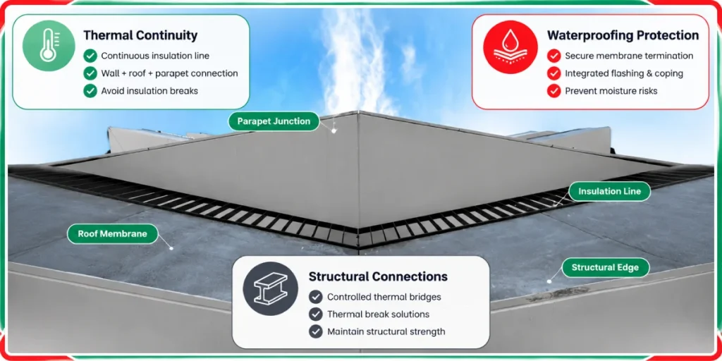
This approach is particularly important on flat roofs because the parapet is often simultaneously a structural edge, waterproofing termination, architectural feature and fall-protection element.
Thermal Continuity
The first question should be: Where is the continuous insulation line?
Draw that line through the wall, roof and parapet section. If it suddenly stops at concrete, metal or another conductive material, investigate the junction.
This simple exercise often reveals problems before detailed thermal calculations are undertaken.
Waterproofing and Thermal Performance
The parapet insulation detail must not compromise waterproofing. Roof membranes normally need reliable upstands, terminations and protection, while the insulation must remain positioned to control heat flow.
A thermal improvement that creates an unreliable membrane termination is not a successful envelope detail. Water ingress can cause substantially more damage than the thermal bridge itself.
For this reason, membrane, flashing, coping and insulation should be drawn together in the same construction detail.
Structural Connections
Structural requirements can create unavoidable conductive paths. Reinforced concrete parapets, slabs, steel brackets and other structural components may need to cross the insulation layer.
The objective is not to eliminate every structural connection. It is to understand where the connection bypasses insulation and determine whether its thermal effect can be reduced through geometry, insulation continuity or an appropriate thermal break.
Structural capacity must always remain the primary constraint for the connection design.
How to Reduce a Parapet Thermal Bridge
Reducing a parapet thermal bridge starts with keeping the insulation layer continuous and then resolving the unavoidable structural and waterproofing constraints around it. The objective is not to make every component thermally identical, but to prevent unnecessary conductive shortcuts through the envelope.
A useful design process is to begin with the building section and mark the intended thermal envelope. The roof insulation, wall insulation and parapet insulation should connect without unexplained gaps, abrupt reductions or exposed structural paths.
Where a conductive connection cannot be avoided, the designer can investigate a thermal break, improved geometry, lower-conductivity connection or alternative construction system. The appropriate choice depends on structural loads, fire requirements, moisture exposure and the overall wall and roof build-up.
| Design Measure | Thermal Benefit | Other Consideration |
| Continuous roof insulation | Reduces heat flow at roof edge | Must coordinate with membrane |
| Continuous wall insulation | Protects wall-to-parapet junction | Façade detailing required |
| Parapet insulation | Raises local surface temperature | Space may be limited |
| Thermal break | Reduces conduction through connection | Structural design required |
| Reduced metal bypasses | Limits local conductive paths | Fixing design must remain adequate |
| Improved junction geometry | Reduces concentrated heat flow | May affect architectural appearance |
| Thermal modelling | Quantifies junction performance | Requires accurate project inputs |
Thermal Modelling of a Parapet Junction
Simple insulation calculations are useful for the main roof and wall areas, but they do not fully describe a complicated parapet junction. Once geometry and different materials meet, heat flow becomes multidimensional.
A two-dimensional thermal model can help identify cold spots, compare alternative thermal bridge roof edge details and assess whether the proposed junction performs adequately. This is particularly useful for buildings with high insulation levels or demanding energy targets.
The model should represent the actual construction as closely as practical. Insulation thickness, concrete, steel, membranes, finishes and connection details can all influence the result. A model based on an idealised junction can give misleading confidence.
What Should Be Checked?
The first check is heat flow through the junction. The second is the internal surface temperature, particularly at corners and areas adjacent to conductive materials.
The designer should also investigate whether the junction creates a meaningful parapet condensation risk under the project’s expected indoor humidity and outdoor temperature conditions.
Thermal modelling should support—not replace—good construction detailing. A theoretically strong result is of limited value if the insulation cannot actually be installed continuously on site.
When Is Detailed Analysis Worthwhile?
Detailed analysis is especially useful for highly insulated buildings, passive or low-energy projects, complicated structural connections and junctions containing substantial metalwork.
It can also be valuable where several possible details are being considered. Instead of relying on assumptions, the project team can compare the thermal behaviour of different solutions before construction.
For conventional projects, the level of analysis should remain proportionate to the building’s performance requirements and applicable regulations.
Parapet Thermal Bridge Construction Details
The construction detail should show the relationship between the structural parapet, roof insulation, wall insulation, waterproofing membrane, flashing and coping.
A typical flat-roof junction might have a structural slab, tapered or flat roof insulation, waterproofing membrane and a parapet extending above the roof surface. The critical area is where the insulation turns or meets the parapet because this is where continuity is most easily lost.
The detail should also be buildable. If an insulation layer exists only as a thin line on a drawing but cannot physically be installed because of brackets, membrane terminations or tolerances, the thermal design has not been fully resolved.
| Detail Element | What to Verify |
| Roof insulation | Continuous to intended edge |
| Parapet insulation | No unnecessary exposed conductive path |
| Wall insulation | Connected to roof-edge insulation |
| Membrane | Correct upstand and termination |
| Flashing | Secure and compatible with waterproofing |
| Coping | Weather protection without excessive thermal bypass |
| Fixings | Thermal bypass considered |
| Drainage | Water directed away from vulnerable junctions |
| Structural connection | Adequate load transfer |
Real Construction Examples
Realistic examples help show why the same parapet strategy cannot simply be copied from one building to another.
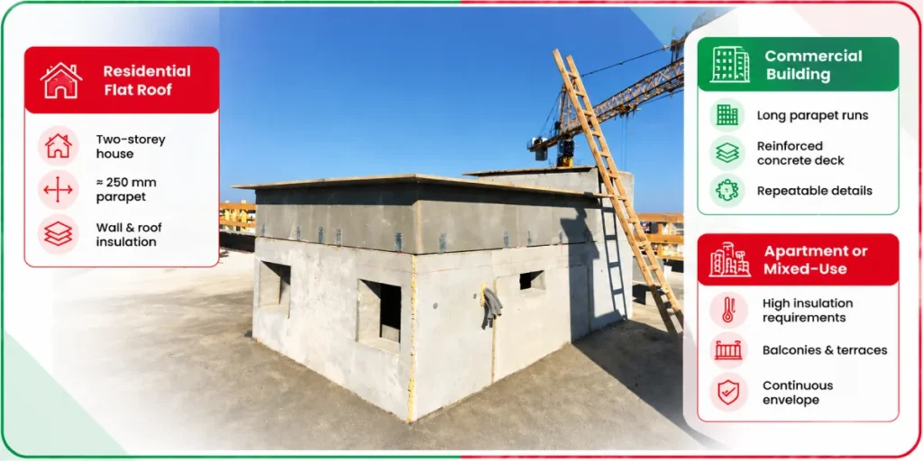
Dimensions below are illustrative design scenarios, not universal standards.
Residential Flat Roof
Consider a two-storey house with a flat roof and an approximately 250 mm structural parapet. The external wall uses continuous external insulation, while the roof has a substantial insulation layer above the structural deck.
The critical detail occurs where the wall insulation meets the parapet and roof insulation. If the concrete parapet remains exposed internally without adequate thermal continuity, it can create a cold strip along the roof perimeter.
A coordinated parapet insulation detail can keep the wall and roof insulation connected while leaving sufficient space for membrane termination and coping. The exact thicknesses should be determined from the project’s energy, structural and moisture requirements.
Commercial Building
A commercial building may have several hundred metres of parapet around its roof. Even a modest junction weakness can therefore become relevant because the same detail is repeated around the entire perimeter.
Suppose the roof uses a reinforced concrete deck and the parapet is structurally integrated with the slab. The design team needs to examine the concrete path through the insulation rather than considering only the roof’s nominal insulation value.
A repeatable detail is particularly valuable here. Factory-produced or prefabricated components can potentially improve dimensional consistency and reduce variation between individual roof-edge sections.
Apartment or Mixed-Use Building
An apartment building can combine high insulation requirements with balconies, terraces and complex façade junctions. Parapets may also need to accommodate guardrails, coping and drainage.
In such a building, thermal bridging can occur at several related junctions rather than one isolated location. A consistent insulation strategy should therefore be developed across roof edges, balcony edges and parapet connections.
The objective is a continuous envelope that can be reproduced reliably across multiple floors and construction phases.
Common Parapet Thermal Bridging Mistakes
One frequent mistake is stopping the roof insulation at the structural parapet without checking what happens to the thermal path. The detail may appear straightforward on site but create a significant local weakness.
Another mistake is treating insulation thickness as the only thermal-performance variable. A thicker roof board does not automatically solve a conductive concrete or steel connection that bypasses it.
A third problem is late coordination. If waterproofing, coping, structural reinforcement and façade systems are finalised separately, there may be insufficient physical space to maintain continuous insulation.
| Mistake | Consequence | Better Approach |
| Insulation stops at parapet | Cold junction | Continue insulation where feasible |
| Concrete bypasses insulation | Increased heat flow | Review geometry or thermal break |
| Metal brackets ignored | Local thermal bridge | Assess conductive fixings |
| Membrane detailed separately | Conflicting layers | Coordinate thermal and waterproofing detail |
| No construction tolerance | Gaps in insulation | Allow realistic installation tolerances |
| Detail changed on site | Performance uncertainty | Control approved junction details |
Parapet Thermal Bridge Cost Considerations
The cost of improving a parapet junction is not simply the price of additional insulation. Labour, specialist thermal-break products, structural modifications, detailing and installation complexity can all affect the final cost.
For a new building, early coordination is generally more efficient than correcting a thermal bridge after the roof and façade systems have already been designed. Late changes can affect several trades simultaneously.
Lifecycle cost is also relevant. A slightly more carefully engineered junction may reduce heat loss and moisture-related maintenance over the building’s service life.
| Cost Factor | Potential Impact |
| Additional insulation | Material cost |
| Thermal-break components | Specialist material cost |
| Complex fixing | Higher installation labour |
| Thermal modelling | Design cost |
| Waterproofing coordination | Detailing and labour |
| Site modification | Potentially high rework cost |
| Poor thermal performance | Long-term energy and maintenance implications |
Traditional vs Prefabricated Parapet Systems
Traditional parapets are commonly constructed on site using concrete, masonry or other conventional materials. Their performance depends heavily on workmanship, dimensional control and coordination between several trades.
Prefabricated parapet systems, including precast concrete parapet elements, can shift more of the manufacturing process into a controlled factory environment. This can make dimensions, connections and insulation placement more repeatable, although the final performance still depends on correct installation and project-specific detailing.
| Factor | Traditional Construction | Prefabricated Approach |
| Installation | Mostly site-based | More factory preparation |
| Labour | Higher site involvement | Reduced site labour potential |
| Dimensional consistency | Depends on workmanship | Factory-controlled |
| Weather exposure | Greater during construction | Reduced for factory operations |
| Insulation integration | Site coordination | Can be integrated during production |
| Thermal continuity | Detail-dependent | Can be designed into system |
| Programme predictability | More site variables | Potentially more predictable |
| Design flexibility | High | Depends on system |
| Quality control | Site dependent | Greater factory control |
Overtec as an Alternative Approach
Overtec’s approach addresses the parapet as a prefabricated building-envelope component rather than relying entirely on conventional site-built construction. This can be relevant where thermal continuity, installation speed and dimensional consistency are important project considerations.
A factory-produced system can integrate key components before delivery, reducing the number of operations that have to be coordinated at the roof edge. This can help limit site variability and reduce dependence on highly skilled labour for repetitive parapet construction.
Overtec states that its system can achieve up to 67% lower CO₂ emissions compared with conventional alternatives. This is a company claim and should be evaluated against the specific project, system boundary and environmental assessment methodology.
From a thermal perspective, the value of a prefabricated parapet is not simply the material itself. The important question is whether the complete installed junction provides better continuity, fewer uncontrolled gaps and more predictable interfaces between insulation, waterproofing and structure.
A slim profile can also be useful where parapet thickness affects usable terrace or balcony area. Where applicable, reducing the space consumed by the edge construction can provide more usable floor area without simply increasing the building footprint.
The potential benefits can therefore include:
| Overtec Characteristic | Potential Project Benefit |
| Faster installation | Shorter roof-edge construction phase |
| Reduced site labour | Fewer repetitive site operations |
| Reduced skilled-labour dependency | Less reliance on specialist site workmanship |
| Factory precision | More consistent dimensions |
| Insulation integration | Better control of thermal continuity |
| Waterproofing integration | Easier coordination of envelope interfaces |
| Reduced thermal bridging | Potentially improved junction performance |
| Reduced weather dependency | Less exposure during fabrication |
| Lower construction risk | Fewer uncontrolled site variables |
| Slim profile | Potentially more usable terrace/balcony space |
| Lower embodied carbon claim | Overtec states up to 67% lower CO₂ |
| Predictability | More controlled programme and quality |
The system should still be evaluated against the project’s structural loads, fire requirements, waterproofing strategy, thermal calculations and local regulations. Prefabrication does not remove the need for good design; it changes where and how much of the work is controlled.
Parapet Thermal Bridge Design Checklist
Architect Checklist
Confirm the thermal envelope is clearly shown in the wall and roof sections. Check that the roof-edge insulation connects logically with the wall insulation.
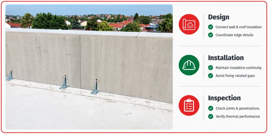
Review coping, flashing, membrane termination and façade interfaces together rather than as independent details. Also check whether the parapet thickness unnecessarily reduces usable terrace or balcony space.
Construction Checklist
Before installation, confirm insulation dimensions, junction tolerances and approved fixing locations. Do not allow site changes that introduce gaps or bypass the intended insulation layer without design review.
Photograph critical junctions before they are concealed where appropriate. This creates useful quality-control evidence for complicated roof-edge construction.
Inspection Checklist
Inspect insulation continuity, membrane termination, flashing, coping and penetrations. Look specifically for compressed, missing or cut insulation around brackets and structural connections.
Where thermal performance is critical, consider whether thermal imaging or other inspection methods can supplement normal visual inspection. Such methods should be interpreted by suitably qualified professionals.
Standards and Technical Requirements
Thermal-bridge design should be coordinated with the energy, structural, fire and waterproofing requirements applicable to the project location. European projects may involve EN standards, Eurocodes and relevant national requirements such as DIN provisions in Germany.
Projects designed under the IBC framework may also need to coordinate energy, structural, fire and fall-protection provisions with the applicable adopted codes. OSHA requirements may become relevant to construction safety and roof-edge work in the United States.
No single code value should be applied universally to every parapet. Requirements depend on building type, climate, construction system and jurisdiction.
Thermal calculations should therefore use the applicable project standards and verified construction build-up. This article is educational guidance, not legal or engineering approval.
FAQs About Parapet Thermal Bridges
It is a localized area of increased heat transfer at a parapet or roof-edge junction, usually caused by insulation discontinuity, conductive materials or complex geometry.
A structural parapet can pass through or around the insulation layer, creating a more conductive route than the surrounding insulated roof and wall.
Not necessarily. Insulation helps maintain thermal continuity, but structural connections, fixings and geometry can still create localized thermal bridges.
A thermal break is a low-conductivity component or layer designed to reduce heat transfer through a specific conductive connection.
They perform different functions. A thermal break can reduce conduction through a connection, while continuous insulation protects the broader thermal envelope.
Yes, if the junction produces a sufficiently cold internal surface under the building’s temperature and humidity conditions.
Maintain insulation continuity, minimise conductive bypasses and assess internal surface temperatures under relevant design conditions.
The insulation strategy should maintain continuity around the junction wherever practical, while still allowing correct waterproofing and structural detailing.
They can be. Conductive metal components that pass through insulation may create localized thermal bridges.
Complex junctions can be evaluated using two-dimensional or three-dimensional thermal analysis based on the actual materials and geometry.
Not automatically. Increasing wall thickness does not necessarily remove a conductive path through the insulation layer.
They can help when thermal continuity is designed and controlled within the prefabricated system, but the installed junction still requires project-specific assessment.
Conclusion: Designing a Better Parapet Thermal Bridge Detail
A parapet thermal bridge is rarely caused by one bad material. It is usually the result of several systems meeting without a sufficiently coordinated thermal strategy.
The most effective approach is to establish a continuous insulation line through the roof, wall and parapet, then resolve structural connections, waterproofing, coping, drainage and fixings around that line.
Where conductive structural connections remain unavoidable, a suitable parapet thermal break or alternative connection strategy can reduce heat flow. Detailed thermal analysis can then verify whether the completed junction performs as intended.
For projects where installation speed, repeatability and reduced site labour are important, prefabricated systems such as Overtec’s approach provide another route to controlling the roof-edge construction process. Overtec states benefits including faster installation, reduced labour dependency, factory precision and up to 67% lower CO₂ emissions; these claims should be evaluated against the project’s specific system and assessment boundaries.
Ultimately, good parapet design is not about adding insulation after the architectural and structural design is finished. It is about treating the roof edge as part of the building’s continuous thermal, waterproofing and structural envelope from the beginning.